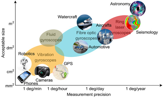

Gyroscopes can seem like simple objects and when the wheel is not spinning, they can be reduced to being over-engineered paperweights. These are typically multi-axis gyroscopes that allow for a wide bandwidth in all their axes. The more complex ones are typically mounted on a metal frame, or set of moveable frames or gimbals for the apparatus to function with greater precision. In their most rudimentary form, gyroscopes are a spinning wheel/disk on an axle. The orientation of the axis is not impacted by the tilting of the mounting, so the gyroscope is in effect used to detect and measure the deviation of an object from its desired orientation, even maintain the said orientation and angular velocity.

#Fiberoptic gyroscope free
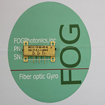
This blog takes a look at all this and more…Ī gyroscope is a device that consists of a wheel or disc or circulating beam of light mounted such that it can spin rapidly about an axis this axis is free to change in any direction. In addition to the standard qualification tests, specific EXALOS’s SLEDs have successfully passed Gama-Radiation testing.What is a gyroscope? You may have heard about the gyroscope but may not know the definition of a gyroscope and where it is used. These qualifications include testing in accordance with MIL-STD-883 and Telcordia. SLED-Transceivers are particularly interesting when realized with a polarization-maintaining (PM) fiber output as they can be directly coupled to the fiber loop of the FOG, avoiding the complexity of realizing a PM fiber coupler.ĮXALOS’ has qualified SLEDs for Space and other Military Applications. SLEDs with this performance will help to reduce the size and cost of FOGs substantially.ĮXALOS has a portfolio of products qualified for FOG applications that require extended operating temperature ranges, increased shock/vibrations levels and verified lifetimes due to their use in space environments.Įxamples of such products include Uncooled Free-Space SLEDs and Cooled & Uncooled Fiber-Coupled SLEDs ) as well as Cooled or Uncooled transceiver modules with an integrated beam splitter and a receiver photodiode. Further work is in progress with the target of achieving wavelength stabilities down to the 10 parts-per-million range. Novel materials and material structures have made it possible to improve the wavelength stability of our devices by a factor of four compared with conventional devices. In the past, wavelength stability over time was a major drawback of semiconductor based broadband light sources like SLEDs compared with fiber-based light sources such as erbium-doped fiber-amplifiers.Īt EXALOS, we have successfully overcome this drawback by developing SLEDs that are less sensitive to wavelength shifts induced by temperature or aging. The key requirements for Fiber Optic Gyroscopes are typically low cost, reduced form factor, low power consumption, long-term stability and high reliability. The phase difference between the two waves varies the intensity at the detector and provides information on the rotation rate. When the coil rotates, the two light waves take different optical path lengths that depend on the rotation rate. When the fiber coil is at rest, the two light waves interfere constructively at the detector and a maximum signal is produced at the demodulator. Light from the source is injected into the fiber in counter-propagating directions using the optical coupler. 1, are a light source, a single-mode fiber coil (could be polarization-maintaining), a coupler, a modulator, and a detector. The basic components of a FOG, as shown in Fig. When a FOG is mounted within a navigation system, it tracks changes in orientation. FOGs measure the Sagnac phase shift of optical radiation propagating along a fiber-optic coil when it rotates around the winding axis. A A key application for SLED is in navigation systems, such as those in avionics, aerospace, sea, terrestrial, and subsurface, that use fiber-optic gyroscopes (FOGs) to make precise rotation measurements.


 0 kommentar(er)
